Symbols act as a common language in the fields of electrical engineering and circuit design, enabling experts to effectively convey complicated concepts. The inductor symbol is one of them that is very important to many circuit diagrams. The complexities, peculiarities, and importance of the inductor symbol in electrical engineering will all be covered in detail in this extensive tutorial.
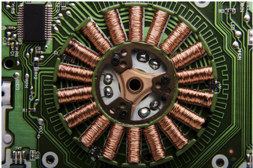
Let us first go over the definition of an inductor before delving into the sign itself. An inductor, sometimes referred to as a coil or choke, is a passive electrical device with two terminals that, when an electric current passes through it, stores energy in a magnetic field. Inductance, the name for this characteristic, is expressed in henries (H). Ersa Electronics provide all kinds of inductor like Fixed Inductors, Adjustable Inductors, and others. If you are interested in that, you can visit this website for inquiry.
The coiled wire that makes up the inductor is represented by a series of loops or curved lines in the conventional inductor symbol. This symbol is easily recognized in circuit diagrams because it graphically represents the fundamental inductor's physical structure.
1. Inductor with Air Core
An air core inductor is usually represented by the basic inductor symbol. When no specific core material is specified, this is the most basic form that is utilized.
2. Inductor with Iron Core
There are parallel lines on one side of the coil loops in the symbol for inductors with an iron core, which raises the inductance. The iron core is represented by these lines.
3. Inductor with Ferrite Core
To depict ferrite core inductors, which are frequently utilized in high-frequency applications, add dots or dashes to one side of the coil symbol.
4. Adjustable Inductor
The traditional inductor symbol is modified to include a diagonal arrow to represent variable inductors, whose inductance is programmable.
5. Inductor using Tape
Additional lines extending from the primary coil sign represent a tapped inductor, which has connections at different points along its length.
Instant Recognition: Inductors in intricate circuit diagrams can be easily recognized by engineers thanks to the inductor symbol.
Design Clarity: It gives precise information on the kind of inductor that was utilized, which is essential to comprehending the behavior of the circuit.
International Standardization: The symbol is widely understood, which makes it easier for engineers from many nations to communicate with one another.
Teaching Tool: The symbol helps students studying electronics by providing a visual representation of the function of inductors in circuits.
Deciphering Inductor Values from Diagrams
The value of the inductor is commonly shown next to the symbol for it in circuit diagrams. For instance, an inductance of 10 microhenries is indicated by the sign "10µH" next to an inductor. One millihenry is denoted as "1mH". Comprehending these symbols is essential for accurately deciphering and executing circuit schematics.
Power supply: The symbols for inductors are commonly encountered in design schematics, and they are essential components of switch-mode power supply.
RF Circuits: Impedance matching and filtering components are represented by inductor symbols in radio frequency applications.
Audio Equipment: Tone controls and crossover networks in audio systems are facilitated by inductors.
Motor Control: Components used for EMI reduction and current smoothing are represented by inductor symbols in motor driver circuits.
Over time, the inductor symbol has stayed mostly the same, with a few small stylistic changes. Modern symbols are simpler to create and recognize than the more literal representations of coiled wires found in early electrical diagrams. The fundamental idea of depicting a coiled wire has remained constant despite numerous modifications.
Inductor symbol representation has grown more consistent since the introduction of electrical engineering CAD software. A wide range of inductor symbols are available in most CAD systems, making it simple for engineers to include many kinds of inductors in their designs.
Misunderstanding Resistor Symbols: Novices occasionally mix up resistor and inductor symbols. It is noteworthy that resistor symbols usually consist of zigzag lines, but inductor symbols are invariably composed of curves or loops.
Incorrect Orientation: In some circuits, especially in linked inductor applications, the orientation of the inductor symbol can be significant.
Errors in Misinterpreting Core Types: In circuit analysis and implementation, misinterpreting the core type (ferrite, iron, or air) can result in serious mistakes.
Despite its straightforward appearance, the inductor symbol contains a multitude of information that is essential to electrical engineering. Knowing the subtleties of the inductor symbol is crucial, regardless of your level of experience constructing complex circuits—whether you're a student just starting out in electronics or an experienced expert.
It is impossible to overestimate the significance of simple, standardized symbols like the inductor symbol as electronics continues to progress. They facilitate innovation and communication within the international engineering community by functioning not only as components of a diagram but also as an essential component of the electrical engineering language.
Gaining proficiency with the inductor symbol and its modifications will provide you access to an essential tool in the extensive toolset of electrical engineering. Keep in mind that every symbol in the complex world of circuit design has a meaning, and the inductor symbol is one that conveys a great deal about the actions and functions of these crucial parts.